
Pressure Reducing
Pressure Sustaining / Pressure Relief
Flow Control valves
Float Valves - Level Control
Electrically Actuated Valves
Pressure Modulation - Remote Control
Altitude Valves - Level Control
Burst Control Valves
Pump Control
CLA-VAL "HYTROL" Main Valve
Valve Controllers and Data Loggers
Air Valves
What Is Tvs Surge Protection and How Does It Work? This question matters wherever sensitive circuits face sudden electrical stress. A relay coil, long cable, or nearby lightning event can create a sharp voltage spike within microseconds. That spike may damage a processor, corrupt stored data, or leave a small black mark on a circuit board.
Tvs Surge Protection uses a transient voltage suppressor diode to limit excessive voltage. Under normal conditions, the diode remains mostly inactive. When voltage rises beyond its designed breakdown level, it conducts rapidly and redirects surge energy away from vulnerable components. The result is called clamping. It reduces the peak voltage reaching the protected circuit, although it does not make the surge disappear.
Small details matter.
This guide explains avalanche breakdown, clamping voltage, peak pulse current, response time, and energy ratings. It also examines unidirectional and bidirectional TVS devices, with examples from USB ports, automotive modules, industrial sensors, and power inputs. A suitable part must match the circuit’s working voltage and expected surge waveform. Choosing only by package size can create false confidence. A diode that looks correct may clamp too high or fail under repeated pulses.
Reliable protection requires more than placing a TVS diode across two traces. PCB layout, grounding, fuse coordination, cable length, and testing conditions strongly influence performance. IEC 61000-4-5 testing can provide useful guidance, but real installations may behave differently. No protector is magic. Careful datasheet review and measured verification remain essential for safe, durable designs.
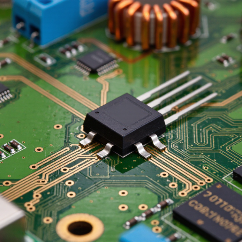
TVS surge protection is a fast electronic defense against brief voltage spikes. A TVS device, usually a specialized diode, sits across a circuit’s power or signal lines. Under normal voltage, it stays nearly inactive. When a transient rises above its breakdown range, the diode enters avalanche conduction and diverts current away from sensitive components. The circuit voltage is clamped to a safer level. It happens in nanoseconds. That speed matters.
These transients can come from inductive motors, relay switching, electrostatic discharge, or nearby lightning activity. Unlike a fuse, a TVS device can respond repeatedly to short events when selected correctly. However, surge protection does not mean unlimited protection. Every device has a standoff voltage, clamping voltage, peak pulse current, and energy rating. Engineers must match these values to the real circuit, not just its nominal voltage. A 12-volt rail, for example, may exceed 12 volts during ordinary operation. That detail is easy to miss.
Effective protection also depends on circuit layout. Keep the path between the protected circuit, TVS device, and ground short and wide. Long traces add inductance and can raise voltage before clamping begins. For data lines, capacitance must remain low, or signal edges may become distorted. Field testing with an oscilloscope and a suitable surge generator can reveal weaknesses that calculations overlook. I would not treat a schematic symbol as proof of safety. Wiring, enclosure design, grounding, and repeated surge exposure still deserve practical review.
TVS surge protection controls excess voltage by diverting it, not by absorbing every joule indefinitely. Under normal voltage, the diode remains nearly inactive. When a fast transient exceeds its breakdown voltage, its resistance drops sharply. Current then flows through the TVS path, limiting the voltage reaching sensitive circuits. The response usually occurs within nanoseconds. However, the clamping voltage changes with surge current, temperature, and PCB layout.
IEC 61000-4-5:2014 specifies surge testing for equipment, including power-port test levels up to 4 kV under defined coupling conditions. IEEE C62.41.2 also classifies surge environments and waveforms used in low-voltage AC systems. These figures are test conditions, not promises of universal protection. A common mistake is selecting a diode by standoff voltage alone. Designers should compare peak pulse current, clamping voltage, rated power, and the actual transient waveform. A short trace can still create damaging inductive voltage. The simple explanation misses that detail.
Tips: Place the TVS diode close to the connector. Keep the return path short and wide. Check both positive and negative surge behavior. Validate the final circuit with IEC testing, because bench simulations may overlook grounding inductance. Also, avoid choosing the lowest clamping voltage automatically; leakage current and signal integrity may suffer. That trade-off deserves review.
| Data Dimension | Technical Data or Typical Range | How It Relates to TVS Surge Protection |
|---|---|---|
| Primary Function | Limits short-duration overvoltage transients by diverting surge current away from protected circuitry. | A TVS diode acts as a fast shunt protection device rather than a voltage regulator for continuous overvoltage. |
| Normal Operating State | Very high impedance below the specified reverse working voltage, with only a small leakage current. | The protected circuit normally operates without significant current flowing through the TVS diode. |
| Voltage Trigger Point | The diode begins entering avalanche conduction when the transient voltage rises above its breakdown region. | Avalanche conduction causes the TVS diode to provide a low-impedance path for the excess surge current. |
| Response Time | Typically in the sub-nanosecond to low-nanosecond range for the semiconductor junction; the complete circuit response also depends on layout and parasitic inductance. | Short, low-inductance connections are essential because PCB trace inductance can increase the voltage seen by the protected load. |
| Reverse Working Voltage (VRWM) | The maximum continuous reverse voltage that can be applied without causing significant avalanche conduction. Common design values range from about 3 V to more than 100 V, depending on the application. | VRWM should be higher than the highest normal steady-state voltage, including supply tolerance and expected operating variation. |
| Breakdown Voltage (VBR) | The voltage range at which a specified test current flows through the diode. It is higher than VRWM. | VBR indicates when the protection device starts to conduct substantially, but it is not the final clamping voltage. |
| Clamping Voltage (VC) | The maximum voltage measured across the TVS during a specified surge current and waveform. Typical values may be approximately 1.3 to 2 times VRWM, depending on device design and test conditions. | VC is the key value used to verify that the protected component can withstand the remaining transient voltage. |
| Peak Pulse Current (IPP) | The maximum rated surge current for a specified pulse waveform, commonly the 10/1000 µs waveform for power transient ratings. | The TVS must be selected so its IPP rating is equal to or greater than the expected surge current under the relevant waveform. |
| Peak Pulse Power (PPP) | The maximum transient power rating, calculated approximately as PPP = VC × IPP for the specified test conditions. | Power ratings are pulse-dependent; a device rated for a particular surge waveform may not withstand the same power for a longer or different pulse. |
| Typical Pulse Ratings | Small signal and data-line parts may be rated from tens to hundreds of watts, while larger discrete TVS devices may be rated from several hundred watts to several kilowatts for short pulses. | The correct rating depends on surge source, pulse duration, repetition rate, thermal conditions, and package construction. |
| Unidirectional Configuration | Provides avalanche protection in the reverse direction and behaves similarly to a conventional diode in the forward direction. | Often used on DC power rails and circuits where the signal polarity is known. |
| Bidirectional Configuration | Provides similar clamping behavior for positive and negative transients. | Commonly used on differential, alternating-current, and communication lines where both voltage polarities must be protected. |
| Leakage Current | Usually specified at VRWM; values range from nanoamps or microamps for low-leakage signal protectors to higher levels for high-power devices. | Low leakage is important for battery-powered systems, precision analog inputs, and high-impedance signal lines. |
| Junction Capacitance | Can range from less than 1 pF for high-speed data protection to hundreds or thousands of pF for larger power devices. | Lower capacitance reduces signal distortion and is preferred for high-speed interfaces. |
| Energy Absorption Mechanism | The avalanche junction converts part of the transient electrical energy into heat during the pulse. | The device must have sufficient pulse-energy and thermal capability to avoid damage or excessive temperature rise. |
| Common Surge Sources | Electrostatic discharge, inductive switching, cable transients, load-dump events, lightning-induced surges, and power-supply disturbances. | The surge type determines the required clamping level, current rating, pulse duration, and protection topology. |
| Protection Placement | Place the TVS close to the connector or surge entry point, with a short and wide path to the return or ground plane. | Good placement minimizes parasitic inductance and prevents transient current from passing through sensitive circuit areas. |
| Selection Rule | Choose a device with VRWM above the normal maximum voltage, VC below the protected circuit's maximum withstand voltage, and adequate IPP and PPP ratings. | A device with an unnecessarily low VRWM may conduct during normal operation, while an excessive VC may fail to protect the load. |
| Important Limitation | A TVS diode is primarily intended for transient protection and should not be used as the sole protection against sustained overvoltage or repeated high-energy faults. | Fuses, current limiters, regulators, transient filters, or other protective stages may be required for complete system-level protection. |
A TVS surge protection system is more than one protective diode. Its core component is the TVS diode, which stays nearly invisible during normal voltage. When a transient rises above its breakdown level, the diode avalanches and diverts current toward ground. Response time is typically measured in picoseconds, but protection depends heavily on the surrounding circuit.
The main components include a TVS diode, a fuse or resettable protector, series impedance, decoupling capacitors, and a low-inductance ground path. The fuse limits sustained fault current. Series impedance reduces surge energy before it reaches sensitive circuitry. Capacitors handle fast noise, while the PCB ground path carries diverted current safely. IEC 61000-4-5 defines surge testing with 1.2/50 microsecond voltage and 8/20 microsecond current waveforms. It also specifies test levels up to several kilovolts, depending on the port and environment. These figures show why layout matters as much as component selection.
Tips: Keep the TVS diode close to the connector. Use short, wide traces. Avoid sharp routing turns. Select standoff voltage above the circuit’s maximum operating voltage. Check clamping voltage under the expected peak current, not only the catalogue value. A common design mistake is choosing a powerful diode with a weak ground return. The diode survives, but the protected circuit may not. Test the complete assembly under realistic cable length, grounding, and surge conditions. Perfect assumptions rarely survive the bench.
This representative waveform shows how a bidirectional TVS diode can limit a short transient on a nominal 24 V DC line. Without protection, the surge may rise far above the circuit rating; with TVS protection, the voltage is clamped to a safer level within nanoseconds.
Lightning-induced surges, inductive switching, and electrostatic discharge can create short high-voltage pulses.
The TVS remains high-impedance during normal operation and rapidly conducts excess current during a surge.
The downstream circuit receives a reduced clamping voltage, while a fuse, resistor, or PCB trace helps manage surge current.
Values are representative engineering data for a 24 V circuit and are not tied to any specific manufacturer or product.
A TVS diode protects a circuit by reacting to excessive voltage within nanoseconds. Under normal voltage, it remains nearly nonconductive. When a surge exceeds its breakdown voltage, avalanche conduction begins. The device then creates a low-impedance path for surge current, limiting the voltage reaching sensitive components.
The process follows a clear sequence. A lightning-induced or switching transient arrives through a power or signal line. The TVS detects the rising voltage and enters conduction.
Surge current flows through the diode toward ground or a return path. Its clamping voltage rises with current, while its dynamic resistance controls the remaining overshoot.
IEEE C62.41.2 references 1.2/50 microsecond voltage and 8/20 microsecond current waveforms for surge testing. IEC 61643-11 also defines performance tests for low-voltage surge protective devices.
Protection is not only about the diode. Trace length, grounding, fuse coordination, and parasitic inductance can change the result. A 2024 industry market report projected the global surge protection device market to grow at roughly 6% annually through the decade. That growth reflects wider use in vehicles, industrial controls, and connected equipment.
Yet a laboratory waveform may look perfect. Installed wiring can disagree. A TVS with a 24-volt standoff rating may clamp too late, while a lower-rated part may leak continuously. Engineers must compare working voltage, peak pulse current, clamping voltage, and repetitive surge exposure before final selection.
TVS devices protect sensitive circuits from short, high-voltage transients. Under normal voltage, the device remains nearly inactive. When a surge exceeds its trigger level, it conducts current away from the protected load. This action limits the voltage seen by processors, sensors, and communication interfaces. The protection is fast, often within nanoseconds. Speed matters when electrostatic discharge reaches a connector.
TVS protection appears in USB ports, automotive control lines, industrial sensors, power inputs, and data interfaces. A device near an exposed cable usually needs stronger surge handling. A high-speed interface needs low capacitance to avoid signal distortion. That balance is not always easy.
Start with the maximum reverse working voltage, or VRWM. It must exceed the circuit’s highest normal operating voltage. Check breakdown voltage, clamping voltage, and peak pulse current under the same test conditions. A low clamping voltage sounds attractive, but it may require higher leakage or a larger package. Polarity also matters. Unidirectional parts suit many DC rails, while bidirectional parts often fit signal lines and alternating waveforms. Package size, thermal paths, and PCB trace length affect real performance. Keep the TVS close to the entry point, with short and wide connections to ground.
Datasheets can look precise. Real surges are less tidy. Cable length, grounding, and installation often change the result. A practical design should test the complete assembly, not only the component. Rechecking assumptions is worthwhile. A part selected from voltage ratings alone may still fail during repeated pulses.
CLA-VAL UK Limited
Dainton House
Goods Station Road
Tunbridge Wells
Kent, TN1 2DR
© 2025 CLA-VAL UK | site map | Terms and Conditions of Sale and Warranty | Privacy policy