
Pressure Reducing
Pressure Sustaining / Pressure Relief
Flow Control valves
Float Valves - Level Control
Electrically Actuated Valves
Pressure Modulation - Remote Control
Altitude Valves - Level Control
Burst Control Valves
Pump Control
CLA-VAL "HYTROL" Main Valve
Valve Controllers and Data Loggers
Air Valves
Choosing a Ptfe Elgiloy Lip Seal requires more than matching a catalog number. The seal must survive real motion, pressure changes, temperature swings, and chemical exposure. A laboratory result may look excellent, yet field conditions can be less forgiving.
Tribologist Bharat Bhushan defines the discipline clearly: “Tribology is the science and engineering of interacting surfaces in relative motion.” That principle guides every reliable seal decision. The PTFE lip must support low friction and chemical resistance. The Elgiloy energizer must maintain contact without losing resilience. Small details matter. Shaft hardness matters. Surface finish matters. So does installation cleanliness.
This guide presents seven practical tips for selecting the right Ptfe Elgiloy Lip Seal. It examines operating temperature, pressure, speed, media compatibility, shaft condition, energizer requirements, and installation limits. Each factor can change service life. Ignoring one may create leakage, wear, or unexpected downtime.
Experience also teaches restraint. A seal rated for a demanding application may still fail under misalignment or dry running. Ratings are not guarantees. They are boundaries.
The best choice begins with measured operating data, not assumptions. Record the actual temperature near the lip. Check the shaft finish with suitable inspection tools. Confirm chemical exposure during cleaning and production cycles. Then compare those findings with the manufacturer’s technical data.
Some applications remain uncertain. That is normal. A controlled trial, inspection plan, and documented feedback can reveal weaknesses before full deployment. Good engineering leaves room for revision.
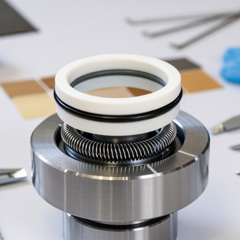
Choosing a PTFE Elgiloy lip seal begins with defining its operating conditions, not selecting materials from a catalog. Record pressure, temperature, shaft speed, fluid, duty cycle, and leakage tolerance. A seal running at 180°C in clean hydraulic oil faces different risks than one exposed to abrasive dust and frequent starts.
Published tribology data commonly places PTFE’s friction coefficient near 0.05–0.15, but actual values change with load, finish, lubrication, and temperature. ISO 23936-2 also emphasizes material qualification under application-specific pressure, temperature, and fluid exposure. These figures are useful, not absolute. Field conditions often disagree.
Measure the shaft surface carefully. A rough shaft can wear the lip quickly, while an overly smooth surface may retain too little lubricant. For many rotary sealing systems, shaft speeds around 1,000–3,000 rpm require close control of heat and contact pressure. Confirm the pressure differential during start-up, shutdown, and reverse rotation. The highest load may occur briefly.
Check chemical compatibility with the actual fluid, additives, cleaning agents, and process residue. Elgiloy supports strong corrosion resistance, but spring performance still depends on temperature and stress history. ASTM-style immersion tests can reveal swelling, cracking, or loss of elasticity, yet they may not reproduce dynamic wear. That gap deserves attention. I would also question any rating based only on room-temperature testing. Real equipment rarely stays that polite.
Tip 1: Match the PTFE compound to the fluid and temperature range. PTFE offers low friction and strong chemical resistance, but it can creep under constant pressure. Check pressure, speed, thermal cycling, and media compatibility together. A seal that works in clean water may fail quickly with abrasive powder or aggressive chemicals. Small details matter.
Tip 2: Select the Elgiloy spring for the actual operating environment. This corrosion-resistant cobalt alloy can maintain spring force across demanding temperatures and repeated cycles. However, spring load must suit the seal groove, pressure, and contact surface. Excessive load can increase friction and shaft wear. Insufficient load may allow leakage during startup.
Tip 3: Inspect the mating hardware before choosing the seal. PTFE lip seals perform best with a smooth, properly finished shaft and controlled runout. Confirm groove dimensions, shaft hardness, pressure direction, and installation clearance. Field reviews often reveal hardware problems, not material problems. I have seen good seals underperform because installation tools scratched the lip. That mistake is easy to miss.
Do not rely on a material chart alone. Test the seal with the real fluid, temperature changes, pressure pulses, and cleaning cycle. A perfect match is rare. The practical choice balances chemical resistance, spring recovery, friction, service life, and maintenance access. When evidence is limited, document the assumption and plan a controlled trial.
| Tip | Application Factor | Relevant PTFE Property | Relevant Elgiloy Spring Property | Selection Guidance |
|---|---|---|---|---|
| 1 | Temperature range | PTFE has a broad service range and a melting point of approximately 327°C. Its practical seal limit depends on pressure, load, design, and the specific compound. | Elgiloy is a cobalt-based alloy with strong resistance to oxidation and high-temperature strength retention compared with many common spring alloys. | Select a grade and design that cover both the continuous and peak temperatures. Confirm stress relaxation and material compatibility at the actual operating temperature. |
| 2 | Pressure and extrusion risk | PTFE has low friction and excellent chemical resistance, but unfilled PTFE can deform or extrude under high pressure, especially with a large clearance gap. | The spring mainly maintains sealing force; it does not replace proper anti-extrusion design or adequate gland support. | Check pressure, clearance, temperature, and dynamic speed together. Use a filled PTFE compound, a back-up feature, or a tighter gland design when extrusion is possible. |
| 3 | Chemical exposure | PTFE is resistant to most chemicals, including many acids, bases, solvents, and fuels. Exceptions and permeation effects still require verification. | Elgiloy provides good corrosion resistance in many demanding environments, but aggressive halides, strong acids, and other specific media must be evaluated. | Review the complete media composition, concentration, temperature, pressure, and exposure time. Check both the PTFE compound and the energized spring. |
| 4 | Motion and friction | PTFE offers a low coefficient of friction and is suitable for reciprocating, rotary, and static sealing when the surface finish and lubrication conditions are appropriate. | The spring must provide stable contact force without excessive loading that could increase wear or friction. | Specify shaft or bore speed, stroke, oscillation, start-stop frequency, surface hardness, and finish. Validate wear and heat generation under representative cycling. |
| 5 | Spring energizer selection | The PTFE jacket supplies the primary sealing interface, while the spring compensates for material deformation, dimensional variation, and wear. | Elgiloy combines high strength, good fatigue performance, and useful corrosion resistance for many high-demand applications. | Choose a spring type and load that match the seal diameter, motion, pressure direction, installation method, and required deflection. Avoid over-compressing the energizer. |
| 6 | Permeation and leakage control | PTFE has very low absorption and strong chemical resistance, but gases and low-viscosity fluids can permeate through or around a seal under pressure. | A corrosion-resistant spring helps maintain contact force, but it cannot eliminate permeation through the polymer or leakage caused by poor gland design. | Define the allowable leakage rate and test method. Consider pressure cycling, vacuum conditions, gas type, temperature, surface finish, and seal orientation. |
| 7 | Installation and gland design | PTFE has limited elasticity compared with elastomers and can be damaged by sharp edges, twisting, excessive stretching, or incorrect compression. | The spring must remain correctly positioned and able to energize the sealing lip after installation. | Use lead-in chamfers, protect the seal from threads and ports, control gland dimensions, and verify spring orientation. Test the installed assembly rather than relying only on material data. |
Note: Actual pressure, speed, temperature, clearance, leakage, and chemical-resistance limits depend on the PTFE formulation, seal geometry, surface condition, gland design, and operating cycle. Confirm the final selection through application-specific testing.
Choosing a PTFE lip seal begins with geometry, not material alone. In service, the lip must match pressure, speed, shaft finish, and temperature. A single pressure lip suits many rotating shafts when leakage control is straightforward. A secondary dust lip adds protection, but it also increases friction and heat. Keep it simple when contamination is limited.
The contact design controls sealing stability. A narrow, well-supported lip can reduce drag and heat at high shaft speeds. A wider contact band may improve low-pressure sealing, but it can wear faster. Set the lip interference carefully. Excessive interference creates torque, temperature rise, and early wear. Insufficient interference may cause leakage during start-up. The energizing spring should maintain contact as PTFE relaxes over time. Its cavity must also prevent tilting during assembly.
I have seen good calculations fail because the shaft finish was ignored. A polished shaft is not always better; excessive smoothness can retain too little lubricant. Small surface grooves may cut the lip. Pressure direction matters, too. The pressure-facing lip should receive firm support, especially during pressure spikes. Test the seal with the actual shaft coating, lubricant, and temperature cycle. Bench results can mislead. A design that works for ten hours may change after thermal cycling. Leave room for revision. That is not weakness; it is sound engineering.
The chart shows practical starting ranges for key lip-seal geometry variables. Narrower contact bands generally reduce friction and heat generation, while wider contact bands can improve sealing robustness. Final dimensions should be verified against pressure, shaft speed, temperature, surface finish, and PTFE grade.
Use a smaller contact width and lower radial interference for high-speed rotary service. Use a wider contact band and greater interference when leakage control and pressure resistance are more important than friction reduction. A rounded or chamfered lead-in helps protect the lip during installation.
Choosing a PTFE lip seal starts with the medium, not the catalog number. PTFE resists many acids, solvents, and hydrocarbons, but additives can change its behavior. Check concentration, moisture, particles, and cleaning chemicals. ISO 23936-1 highlights material compatibility as a key factor in oil and gas sealing applications. A fluid chart helps, but it is not enough.
Temperature needs a real operating profile. ASTM D4894 data places PTFE’s melting point near 327°C, while practical continuous service is often limited to about 260°C. Do not confuse melting temperature with safe sealing temperature. Thermal cycling can harden the lip or relax the spring. Record startup, shutdown, frictional heating, and nearby equipment heat. Small details matter.
Pressure is less forgiving. A seal may tolerate high pressure at low speed, then fail when pressure, shaft speed, and temperature rise together. Confirm extrusion gaps, surface finish, and pressure direction against the supplier’s test data. NORSOK M-710 is useful when rapid gas decompression is possible. The corrosion-resistant cobalt alloy spring also needs media verification. We sometimes overtrust “chemically resistant” labels. That is a mistake worth challenging. Test a sample under actual pressure, temperature, and fluid conditions before approving production use.
Installation details often determine whether a PTFE lip seal performs for months or fails within hours. Confirm shaft diameter, runout, surface finish, housing tolerance, pressure, speed, and temperature before ordering. The mating shaft should be clean and free from scratches. Even a tiny burr can cut the sealing lip during assembly. Check the sealing direction carefully. A reversed lip may look acceptable, yet leak immediately under pressure. Use the specified lubricant, if permitted, and avoid tools that stretch or distort the seal.
Expected service life needs evidence, not optimism. PTFE can deform under heat, pressure, and continuous load. Its spring energizer also requires chemical compatibility with the operating fluid. ISO 19973-1 provides a framework for reliability testing, but laboratory cycles cannot reproduce every field condition. Ask for test temperature, pressure, speed, leakage limits, and cycle count. A life claim without these details is incomplete. It happens often.
The U.S. Department of Energy reports that compressed-air leaks can waste 20–30% of compressor output. Poor sealing can therefore raise energy costs, not merely create visible leakage. Plan an installation inspection after the first operating cycle. Record leakage, shaft condition, and temperature trends. Review those records honestly. A seal selected from a catalog alone may be convenient, but it is not a service-life calculation.
CLA-VAL UK Limited
Dainton House
Goods Station Road
Tunbridge Wells
Kent, TN1 2DR
© 2025 CLA-VAL UK | site map | Terms and Conditions of Sale and Warranty | Privacy policy