Pressure Reducing
Pressure Sustaining / Pressure Relief
Flow Control valves
Float Valves - Level Control
Electrically Actuated Valves
Pressure Modulation - Remote Control
Altitude Valves - Level Control
Burst Control Valves
Pump Control
CLA-VAL "HYTROL" Main Valve
Valve Controllers and Data Loggers
Air Valves
Choosing a Water Pressure Reducing Valve is not simply a matter of matching pipe threads. It requires a clear understanding of your plumbing system, water pressure, and daily usage. A home may record 90 psi at night, then fall sharply when several fixtures operate. That change can stress washing machines, heaters, faucets, and hidden pipe joints. This guide explains how to select a valve that provides stable pressure without restricting necessary water flow.
A reliable decision begins with measured inlet pressure, desired outlet pressure, flow rate, and pipe size. Use a calibrated pressure gauge at different times, not only during quiet hours. Check the manufacturer’s flow chart before trusting a valve’s advertised size. For example, a small valve may cause noise or weak showers when multiple appliances run. Valve materials should also suit the water quality and installation environment. Lead-free certification and local plumbing requirements deserve careful attention. Small details matter.
Practical inspections show that maintenance access is often ignored. Leave room for the adjustment screw, pressure gauge, and replacement parts. Follow the manufacturer’s instructions and applicable plumbing codes during installation. A qualified plumber can verify sizing, thermal expansion protection, and safe connections. Still, no selection method is perfect. Even experienced installers can overlook pressure changes caused by pumps or elevated storage tanks. That possibility deserves a second check. The following sections compare valve types, specifications, installation factors, and maintenance needs, helping readers make a safer, more informed choice.
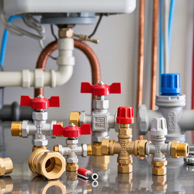
A water pressure reducing valve, or PRV, lowers excessive incoming pressure before water reaches household fixtures. It protects pipe joints, washing machines, heaters, and faucets from stress. The 2024 International Plumbing Code requires pressure control when static supply pressure exceeds 80 psi. Many residential systems operate more comfortably near 50–60 psi, although the correct setting depends on building design and local requirements.
The main type is the direct-acting, spring-loaded PRV. It is compact, affordable, and suitable for most homes. A pilot-operated valve offers tighter control in larger buildings or systems with changing demand. Adjustable models allow technicians to fine-tune outlet pressure, while preset models reduce user error. The choice should consider flow rate, inlet pressure, pipe size, maintenance access, and water quality. A valve that is too small may create noise and pressure loss.
Water pressure also affects consumption. The U.S. Environmental Protection Agency’s WaterSense program reports that household leaks waste nearly one trillion gallons of water annually in the United States. High pressure is not responsible for every leak, but it can worsen weak connections and worn seals. A pressure gauge should be installed downstream for verification. Do not rely only on factory settings. I have seen specifications look correct on paper, yet pressure fall sharply when several fixtures run together. That mistake deserves a second check. Fresh measurements are more reliable than assumptions.
Checking water pressure is the practical starting point. Attach a reliable gauge to an outdoor hose connection or laundry faucet. Record the pressure when no fixtures are running. Then open a nearby faucet and note the drop. Static pressure can look acceptable, while working pressure becomes too low.
Measure flow during realistic demand. Run a shower, flush a toilet, and use another faucet if that matches household use. Time how long it takes to fill a container. This rough test exposes restrictions that pressure alone cannot show. A valve must handle the expected flow without creating excessive pressure loss. A simple estimate can mislead, so repeat the test during busy hours.
Check the system requirements before selecting the valve. Confirm pipe size, connection type, temperature range, adjustment range, and maximum inlet pressure. The outlet pressure should protect fixtures while supporting showers, appliances, and irrigation needs. Many homes work near 50–60 psi, but local requirements and equipment instructions may differ. Install the valve where it remains accessible for adjustment and maintenance. Add a pressure gauge downstream when possible. It makes future diagnosis much easier. Do not ignore water hammer, rust, or a clogged strainer. These problems may imitate valve failure. My first pressure reading would not be enough; I would verify it under flow and inspect the entire supply path.
How to Choose a Water Pressure Reducing Valve?
Selecting the Correct Valve Size, Materials, and Pressure Range
Choosing a pressure reducing valve starts with measured conditions, not the pipe diameter alone. In field inspections, I check inlet pressure, required outlet pressure, peak flow, and minimum flow. A valve that is too small may create noise and excessive pressure loss. An oversized valve can hunt, cycle, or regulate poorly during low demand. The pipe size is only a useful starting point.
Material selection depends on water quality, temperature, and installation conditions. Brass suits many indoor water systems, while stainless steel offers stronger corrosion resistance in demanding environments. Confirm that wetted materials meet applicable drinking-water requirements. Seals also matter. Chlorinated water, heat, or cleaning chemicals can shorten elastomer life. I once focused too heavily on body material and overlooked seal compatibility. That mistake was avoidable.
Pressure range deserves careful attention. Select a valve whose adjustment range includes the target outlet pressure without operating at its limit. Measure both static pressure and pressure during flow. A reading of 60 psi at rest may fall sharply when several fixtures operate. Install pressure gauges before and after the valve, with isolation valves and a cleanable strainer where practical. Set the outlet gradually, then test toilets, showers, and appliances together. A specification sheet may look convincing, but actual system behavior still needs verification.
| Nominal Valve Size | Common Pipe Size | Indicative Flow Range1 | Typical Applications | Recommended Body Materials | Typical Adjustable Outlet Pressure | Key Selection Check |
|---|---|---|---|---|---|---|
| DN15 / 1⁄2 in | 15 mm / 1⁄2 in | 5–25 L/min | Single fixtures, small apartment branches, drinking-water points | DZR brass, stainless steel, or approved lead-free brass | 1.5–6 bar / 22–87 psi | Confirm that the valve can maintain the required flow without excessive pressure drop. |
| DN20 / 3⁄4 in | 20 mm / 3⁄4 in | 10–45 L/min | Residential branches, small irrigation zones, water heaters | DZR brass or stainless steel for corrosive environments | 1.5–6 bar / 22–87 psi | Size according to peak demand, not only the existing pipe diameter. |
| DN25 / 1 in | 25 mm / 1 in | 20–80 L/min | Whole-house supply, small commercial units, multiple simultaneous outlets | Bronze, DZR brass, stainless steel, or coated ductile iron | 1.5–8 bar / 22–116 psi | Check the required inlet pressure, peak flow, minimum flow, and pressure-loss curve. |
| DN32 / 1 1⁄4 in | 32 mm / 1 1⁄4 in | 35–130 L/min | Large residences, small offices, low-rise commercial plumbing | Bronze or stainless steel; ductile iron for larger valve assemblies | 2–10 bar / 29–145 psi | Allow for future demand and verify that the valve remains stable at low flow. |
| DN40 / 1 1⁄2 in | 40 mm / 1 1⁄2 in | 55–190 L/min | Apartment blocks, commercial branches, process-water lines | Bronze, stainless steel, or epoxy-coated ductile iron | 2–10 bar / 29–145 psi | Compare the valve’s pressure class with the maximum static and surge pressure. |
| DN50 / 2 in | 50 mm / 2 in | 80–300 L/min | Multi-unit buildings, commercial facilities, main distribution lines | Ductile iron with protective coating, bronze, or stainless steel | 2–12 bar / 29–174 psi | Use a flow-based calculation and consider a bypass or parallel arrangement for continuity. |
| DN65 / 2 1⁄2 in | 65 mm / 2 1⁄2 in | 130–500 L/min | Large commercial buildings, institutional water systems | Epoxy-coated ductile iron or stainless steel | 2–12 bar / 29–174 psi | Check flange dimensions, allowable velocity, cavitation risk, and maintenance access. |
| DN80 / 3 in | 80 mm / 3 in | 180–700 L/min | High-demand commercial and industrial water distribution | Epoxy-coated ductile iron or stainless steel trim and internals | 2–16 bar / 29–232 psi | Confirm the selected valve’s rated capacity at the actual inlet-to-outlet pressure ratio. |
| DN100 / 4 in | 100 mm / 4 in | 250–1,000 L/min | Large facilities, campus systems, municipal or industrial branches | Epoxy-coated ductile iron, stainless steel, or corrosion-resistant alloy trim | 2–16 bar / 29–232 psi | Provide isolation valves, pressure gauges, a strainer, and adequate straight-pipe access where required. |
Selection Notes
1 The flow ranges are indicative design ranges for preliminary selection. Actual capacity depends on valve geometry, pressure differential, water temperature, allowable velocity, and the manufacturer’s flow coefficient or performance curve.
Choose the valve using the calculated peak flow and required downstream pressure rather than simply matching the nominal pipe size. Oversizing can cause unstable regulation at low flow, while undersizing can create excessive pressure loss and noise.
For potable-water systems, use materials, elastomers, coatings, and testing approvals that comply with the applicable local drinking-water requirements. Install a pressure gauge downstream and consider a strainer, isolation valves, and a relief valve where downstream equipment requires overpressure protection.
How to Choose a Water Pressure Reducing Valve?
A water pressure reducing valve protects pipes, fixtures, and appliances from excessive supply pressure. Installation method matters as much as valve size. Threaded connections suit many household systems and allow simpler replacement. Union connections are more convenient when the valve needs removal. Flanged models fit larger commercial lines but require accurate alignment and stronger support. Always follow the flow arrow, provide an accessible shutoff, and leave room for a pressure gauge. Local plumbing requirements should guide the final installation.
Features should match actual water demand. An adjustable spring helps fine-tune pressure, while an internal strainer can catch sediment before it damages the valve. Some designs include gauge ports or a bypass arrangement for easier testing. During inspections, I look for stable downstream pressure after several fixtures operate together. A valve that performs well at low flow may struggle during peak use. That detail is easy to overlook.
Tips: Set pressure with a calibrated gauge, not by sound or guesswork. Check for leaks after installation. Clean the strainer periodically, especially in areas with rusty or sandy water. Test pressure changes twice yearly. If adjustment becomes difficult, replace worn internal parts instead of forcing the screw. I once underestimated sediment buildup, and the valve responded slowly afterward. A careful maintenance record would have prevented that oversight.
Comparing installation methods, practical features, and maintenance needs.
The chart uses a generalized engineering score from 1 to 5. Higher scores indicate greater installation complexity, easier isolation for servicing, better maintenance access, or suitability for larger pipe sizes. Threaded and union connections are commonly used for small residential lines, while flanged connections are more suitable for larger or commercial piping systems.
How to Choose a Water Pressure Reducing Valve?
Testing performance matters more than choosing by pipe size alone. Install a calibrated gauge downstream, then record static pressure with every fixture closed. Open a nearby tap and record dynamic pressure under flow. A large pressure drop may indicate an undersized valve, blocked strainer, or unstable supply. The U.S. EPA WaterSense program estimates that household leaks waste nearly 1 trillion gallons of water each year. Correct pressure control can reduce stress on joints, toilets, and appliances, but it cannot repair damaged plumbing.
Adjust the outlet pressure slowly. Turn the adjustment screw clockwise only when the valve instructions confirm that direction increases pressure. Make quarter-turn changes, pause, and check the gauge again. Test at no flow and during flow. A residential setting near 50–60 psi is common, though the building design and local requirements must decide the final value. ASSE 1003 covers performance requirements for water pressure reducing valves, so certification and test records deserve attention. A valve may pass a bench test yet behave poorly with sediment in the line. That is an easy detail to miss.
Tips: Flush the inlet line before testing. Keep one fixture flowing during dynamic checks. Recheck pressure after several hours. If pressure slowly rises while no water flows, inspect the valve seat and consider a thermal expansion issue. I would not trust one reading; temperature, supply demand, and gauge accuracy can distort the result.
CLA-VAL UK Limited
Dainton House
Goods Station Road
Tunbridge Wells
Kent, TN1 2DR
© 2025 CLA-VAL UK | site map | Terms and Conditions of Sale and Warranty | Privacy policy